DIY: How to create bushings
Build replaceable inner bushings for hydraulically or manually articulated arms
MADE to guide motion and control friction, bushings shouldn’t squeak, unless of course maintenance is not possible, or just inconvenient. Then, bushings can squeak; they could whine, too; they may eventually grind, warp and then freeze.
This example of a bushing assembly for a basic articulated arm highlights an important feature: a replaceable inner bushing. There’s also a way to add lubricant.
You can modify the design of this assembly, but remember not to lock the inner replaceable bushing to the pivot pin. Otherwise, there could be noises, preludes to unscheduled shutdowns after other parts in the assembly have worn out unnecessarily.

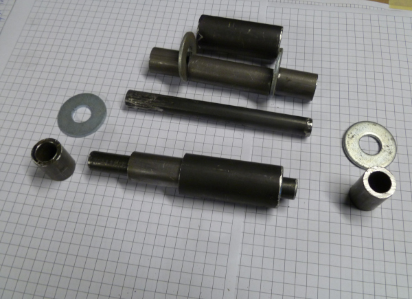
Materials used for this project
Starting in the center of the bushing assembly, a pivot pin serves as a hinge. It’s made of round steel, with a diameter of 0.5 inches.
Slipping over the pin is the inner replaceable bushing, with an outside diameter of 0.75 inches. The inside diameter is 0.51 inches, providing a 0.01-inch differential between itself and the pin.
A larger fixed inner bushing surrounds the replaceable one. It gets welded into the 2-by-2-inch arm, and has an outside diameter of 1 inch. Its inside diameter is 0.76 inches, providing another 0.01-inch gap between itself and the replaceable bushing.
Welded onto opposite sides of the larger 3-by-3-inch arm, fixed outer bushings stabilize the pivot pin. These bushings have an outside diameter of 0.75 inches and an inside diameter of 0.51 inches. The pivot pin will not spin within these bushings, nor will grease be required there. Instead, lock pins get placed in holes that have been drilled in the ends of the pin and bushings. (I personally like to use 3/16-inch lynch pins).
All the bushings are steel tubing, specifically A513 Cold Rolled DOM Steel. DOM stands for “Drawn Over Mandrel,” referring to how the tubing is manufactured to produce its smooth inner bore — no weld seams inside that would hinder movement. DOM Steel tubing is available in many sizes. (I like to shop online when it’s on sale at www.onlinemetals.com.)
Installation sequence
First, consider the overall width you have to work with on the inside of your mounts. In this case, the larger arm is 3-by-3-inch square tubing with walls 1/8 of an inch thick. When the 2-by-2-inch square tubing is centered inside the larger arm, there remains a 3/8-inch space on either side of it for washers and welds.
With this width in mind, cut the pivot pin to a length of 5 inches.
Cut the two inner bushings that run through the 2-by-2-inch arm at a length of 2 1/4 inches. Both ends will protrude out either side of the arm by 1/8 of an inch, forming a lip where the larger 1-inch bushing can be welded to the arm.
Cut the two outer bushings, the ones that will be welded into the 3-by-3-inch arm, at lengths of 1 inch each. They will be placed into the arm, protruding beyond the inner walls of the arm by 1/8 of an inch, again for welding.
Next, “dry fit” the bushings, pin and arms before welding. Check that everything lines up properly, using a level, a square or a straight edge. (I use a bi-metal hole saw in a drill press for the larger holes, giving me nice clearance for the bushings. I use some oil while cutting, so the saw will last a long time.)
Also, make sure your grease fitting that runs through the two inner bushings will be accessible.
Once you’re sure everything is aligned correctly, tack weld the parts in place and test how the articulated arm pivots at this new fulcrum.
If its working well, you can go ahead with your final weld all the fixed parts into place.
| Part | Dimensions | Qty. |
|---|---|---|
| Pivot pin | Diameter: 0.5" Length: 5.0" |
1 |
| Replaceable bushing | Outer diameter: 0.75" Inner diameter: 0.51" Length: 2.25" |
1 |
| Fixed inner bushing | Outer diameter: 1.0" Inner diameter: 0.76" Length: 2.25" |
1 |
| Fixed outer bushings | Outer diameter: 0.75" Inner diameter: 0.51" Length: 1.0" |
2 |
| Washers | Inner diameter: 0.5" Thickness: 0.125" |
2 |
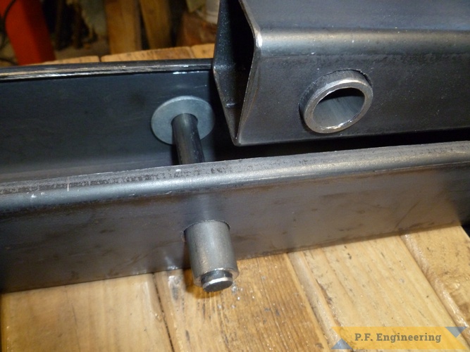
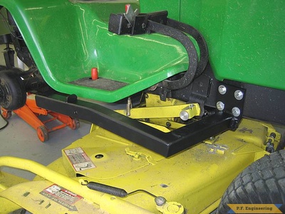
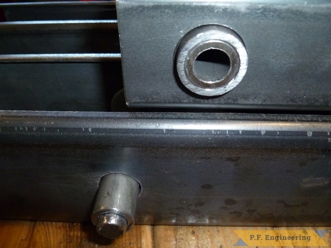
Top right: the larger 1-inch inner bushing placed inside the 2-by-2-inch arm.
The smaller replaceable bushing nested inside the larger inner bushing.
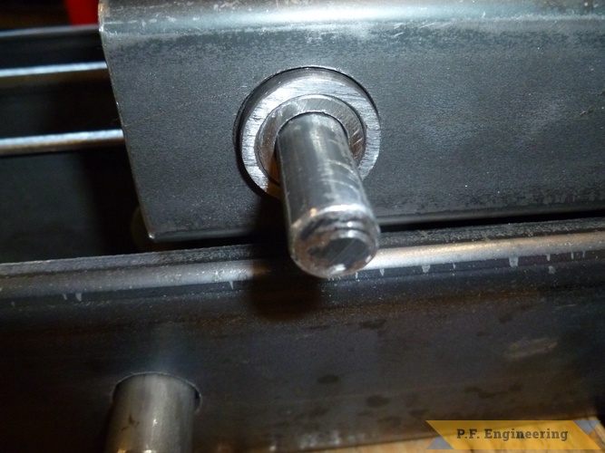
The pivot pin put through the inner bushings.
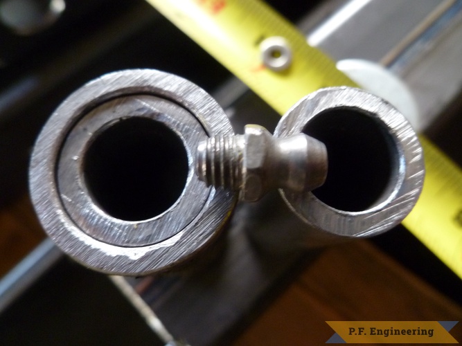
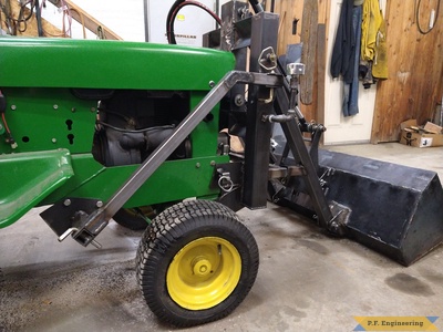
The threaded length of a standard grease fitting measures 7/32 of an inch. The dimensions of the threads themselves are 1/4"-28 taper. The grease fitting will keep the inner bushing in place.
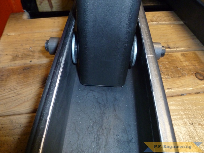
The assembly together with washers and outer fixed bushings.